@@ -198,16 +198,28 @@ Self-balancing robots with gyro sensor
...
@@ -198,16 +198,28 @@ Self-balancing robots with gyro sensor
### Setup
### Setup
The controller used for this exercise is inspired by the controller described in [5]. Unlike previous exercises, this controller is not a regular PID controller, and it monitors two values instead of one; angular velocity and tacho counts of the two motors. The angular velocity is then integrated over time, to obtain the current angle of the robot. The current motor position is calculated as the sum of the tacho count from each motor. The current motor speed is then derived from the position by differentiating the position with regards to time. The controller is thus relying on four terms:
##### Physical Setup
##### Software Setup
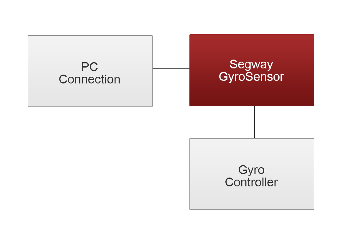
An overview of the software architecture for this exercise is seen in the following image.

The controller used for this exercise is inspired by the controller described in [5]. Unlike the previous exercises, this controller is not a regular PID controller, and it monitors two values instead of one; angular velocity and tacho counts of the two motors. The angular velocity is then integrated over time, to obtain the current angle of the robot. The current motor position is calculated as the sum of the tacho count from each motor. The current motor speed is then derived from the position by differentiating the position with regards to time. The controller is thus relying on four terms:
***GyroAngle:** This term is responsible for causing the robot to return to the starting position (standing upright). If the robot starts in the upright position, that angle will be 0 degrees. This value will be positive if the robot is leaning forward, and negative if its leaning backward, thus contributing to the control output.
***GyroAngle:** This term is responsible for causing the robot to return to the starting position (standing upright). If the robot starts in the upright position, that angle will be 0 degrees. This value will be positive if the robot is leaning forward, and negative if its leaning backward, thus contributing to the control output.
***GyroSpeed:** This term is non-zero when the robot is accelerating, and thus contributes to the control output when the robot is falling.
***GyroSpeed:** This term is non-zero when the robot is accelerating, and thus contributes to the control output when the robot is falling.
***MotorPosition:** This term is non-zero when the wheels of the robot has turned from the starting point. Thus, this term is responsible for keeping the robot stationary, and is not related to staying upright. This term can be used to drive the robot to a desired location, however we did not exploit this fact in this exercise.
***MotorPosition:** This term is non-zero when the wheels of the robot has turned from the starting point. Thus, this term is responsible for keeping the robot stationary, and is not related to staying upright. This term can be used to drive the robot to a desired location, however we did not exploit this fact in this exercise.
***MotorSpeed:** This term is non-zero when the wheels of the robot are rotating. This term keeps the robot from oscillating.
***MotorSpeed:** This term is non-zero when the wheels of the robot are rotating. This term keeps the robot from oscillating.
#### Software Setup
Like in the previous exercises a PC connection class is used to establish a Bluetooth connection between the NXT and the PC letting us choose values for the control parameters on the fly.
The full implementation can be found at [6], with the corresponding PC program located at [7].
The implementation of the controller used in this exercise is inspired by the one described and implemented in [5]. The full implementation can be found at [6], with the corresponding PC program located at [7]. The important parts of the logic are shown in the this section. The following listing shows how calculating angular velocity (`gyroSpeed`) and `gyroAngle` from the raw gyro output is performed:
The important parts of the logic are shown in the this section. The following listing shows how calculating angular velocity (`gyroSpeed`) and `gyroAngle` from the raw gyro output is performed: