@@ -30,21 +30,19 @@ For this exercise we used a LEGO model build according to the description in [2]

We know that the surface which the robot is placed on affects the control mechanism and therefore three different materials are tested. These are a blank white table, a wooden table and a carpet floor which are shown in the following image.
We know that the surface which the robot is placed on affects the control mechanism and therefore three different materials are tested. These are a clean white table, a wooden table and a carpet floor which are shown in the following image.

By inspecting the performance we concluded that the best of the three surfaces was the blank white surface and therefore the following tuning and analysis of the PID parameters are performed on this surface.
We also know that the surrounding light can be a key factor when using a light sensor in a PID control context. Two cases of surrounding light was analyzed; natural light and artificial light. Despite our expectations the surrounding light did not seem to affect the light sensor control mechanism significantly.
We also know that the surrounding light can be a key factor when using a light sensor in a PID control context. Two cases of surrounding light is analyzed; natural light and artificial light.
##### Software setup
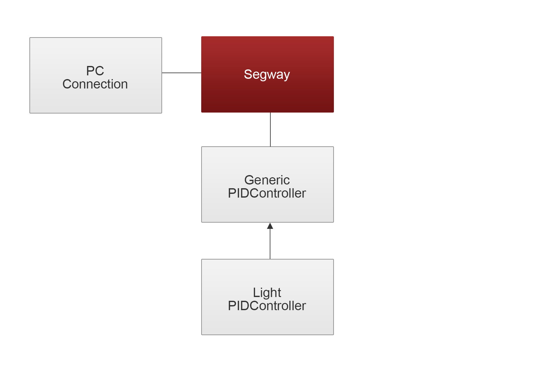
We have created a standard PID software architecture which makes the replacement of a sensor easy. The architecture is shown in the following image.

The architecture consists of a generic PID controller with abstract methods to calculate the error and control signal. The specific PID controller will extend this class and define logic for these methods. The program uses the PCconnection class to establish a Bluetooth connection between the NXT and the PC which is used to pass parameters from a GUI on the PC to the NXT. The GUI is seen in the following image.
The architecture consists of a generic PID controller with abstract methods to calculate the error and control signal. The specific PID controller, in this case the LightPIDController, will extend this class and define logic for these methods. The program uses the PCconnection class to establish a Bluetooth connection between the NXT and the PC which is used to pass parameters from a GUI on the PC to the NXT. The GUI is seen in the following image.

Due to our results from experimenting with the light sensor in lesson 1 we chose to initialize the sensor with the flood light turned on.
The entire code can be seen in [4].
### Results
By repeatedly tuning the parameters through the PC GUI we ended up with the following estimate of the best possible setting of the control parameters:
By inspecting the performance we concluded that the best of the three surfaces was the clean white surface and therefore the following tuning and analysis of the PID parameters are performed on this surface. Despite our expectations the surrounding light did not seem to affect the light sensor control mechanism significantly.
In order to find the most suitable control parameters we started out setting `Kp`, `Ki` and `Kd` to 0 and then adjusting one paramter at a time through the PC GUI. The procedure was the following
1. Setting the paramter to a large value to inspect the effect of the paramter
2. Lowering the value until the performance began to worsen.
By doing this procedure for each parameter we ended up with the following estimate of the best possible setting of the control parameters:
| Parameter | Value |
| ------------- |:------:|
...
...
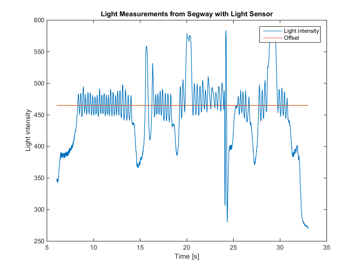
@@ -121,7 +128,9 @@ In order to investigate this behavior the data logger is used to collect the lig

This plot shows the PID controllers offset as the red line and the output of the light sensor as the blue graph.
When the LEGO robot is tilting forward the light sensor will get closer to the surface which yields less light coming in and therefore the output value of the sensor will decrease. On the other hand when the LEGO robot is tilting backwards more light is coming in and the output value will increase. In order for the LEGO robot to keep balance it must constantly try to keep an upright position by applying motor force in the tilting direction (forward or backward). Due to the LEGO robots high center of gravity it is difficult to maintain an upright position resulting in the toggling back and forth between the offset until it is no longer able to adjust for the tilting.
When the LEGO robot is tilting forward the light sensor will get closer to the surface which yields less surrounding light coming in. However the output value will increase due to the light sensors ambient light making reflections on the surface. In contrast when the robot is tilting backward the output value of the sensor will decrease due to less reflected light coming in.
In order for the LEGO robot to keep balance it must constantly try to keep an upright position by applying motor force in the tilting direction (forward or backward). Due to the LEGO robots high center of gravity it is difficult to maintain an upright position resulting in the toggling back and forth between the offset until it is no longer able to adjust for the tilting.
## Exercise 2
...
...
@@ -129,12 +138,35 @@ When the LEGO robot is tilting forward the light sensor will get closer to the s
Self-balancing robots with color sensor
### Setup
For this exercise we used a LEGO model build according to the description in [3] with some minor modifications. Since the upright motor is not used in the case of a segway, the movement of the upper body of the rider has been fixed. Furthermore the motors that are driving the wheels are connected to motor port A and C instead of A and B, in order to utilize both H-bridges. An image of the robot is seen in the following image.
This robot is tested
##### Physical setup
For this exercise we used a LEGO model build according to the description in [3] with some minor modifications. Since the upright motor is not used in the case of a segway, the movement of the upper body of the rider has been fixed. Furthermore the motors that are driving the wheels are connected to motor port A and C instead of A and B, in order to utilize both H-bridges.
In general this robot construction is taller than the NXTway [2] but still it has a lower center of gravity. The wheels has been changed to a slightly smaller pair which are more flat giving the robot more contact with the surface. We estimate that these changes will improve the control mechanism. A color sensor is mounted on the lower part of the robot in a height of approximately 1.5 cm above the surface similar to the sensor placement in exercise 1.
An image of the robot is seen in the following image.

The procedure for testing this robot is similar to the procedure in exercise 1. The same surfaces and light conditions are analyzed according to control mechanism.
##### Software setup
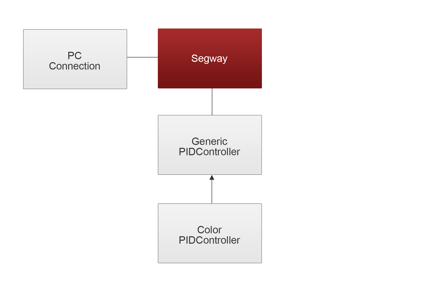
In this exercise the software architecture as in exercise 1 is used but the LightPIDController class is substituted with the ColorPIDcontroller class.

Due to our results from experimenting with the color sensor in lesson 1 we also in this exercise chose to initialize the sensor with the flood light turned on.
### Results
The initial test with random control parameters showed by inspection that also for this robot construction and color sensor that the clean white surface was the best of the three. According the surrounding light we exprirenced a significantly difference between natural light and artificial light where the robot performed much better when surrounded by artificial light.
In order to find the most suitable control parameters the robot is placed on the white surface in a room only lit by artificial light and then the same procedure as in exercise 1 is followed. Starting out setting `Kp`, `Ki` and `Kd` to 0 and then adjusting one paramter at a time through the PC GUI.
By doing this procedure for each parameter we ended up with the following estimate of the best possible setting of the control parameters
| Parameter | Value |
| ------------- |:------:|
| Kp | 7.5 |
...
...
@@ -143,8 +175,22 @@ This robot is tested
| Offset | 480 |
| Min power | 80 |
A video of the robot balancing with these control parameters applied on the white surface in natural lighting is found in the references section. During self-balancing the robot is not able to keep the exact position as placed in initially. The algorithm causes the robot to drift across the table making it finally fall of the table. Until this occur the robot self-balances for ~25 seconds (The video starts after the robot has balanced for ~10 seconds).
In order to compare these results with the results of exercise 1 the data logger is used to collect the color sensor readings during the execution of the program. The end result of this is seen in the following image.

This plot shows the light intensity given by the color sensor as the blue graph and the offset is the red line.
It is clear that this the configuration in this exercise is far better than the configuration from exercise 1. The light intensity continues to fluctuate around the offset for much longer time. Three times during the run of this program the robot need human assitances in order to stay balanced. This is at `time = 16s`, `time = 26s` and `time = 37s` where the light intensity drops indicating that the robot is tilting backwards.
With the defined parameters the robot is again tested on the aforementioned surfaces. This resulted in the following.
***Carpet**: The robot could not balance at all
***Wooden table**: The robot could balance for 1-3 seconds
***White surface**: The robot could balance for ~30 seconds. Ended by falling of the table.