@@ -14,9 +14,9 @@ The goal of this exercise is to test three different sensors and physical robot
## Plan
The plan is to follow the instructions for Lesson 5 [1]. This plan is divided into three parts:
Build the NXTWay robot and test its self-balancing capabilities using a light sensor and PID control.
Build the NXT Segway with Rider and test its self-balancing capabilities using a color sensor and PID control.
Use the NXT Segway
*Build the NXTWay robot and test its self-balancing capabilities using a light sensor and PID control.
*Build the NXT Segway with Rider and test its self-balancing capabilities using a color sensor and PID control.
*Use the NXT Segway with Rider and test self-balancing capabilities using a gyro sensor and alternative control algorithm.
## Exercise 1
...
...
@@ -26,11 +26,11 @@ Self-balancing robot with light sensor
For this exercise we used a LEGO model build according to the description in [2]. Our final model is shown in the following image.


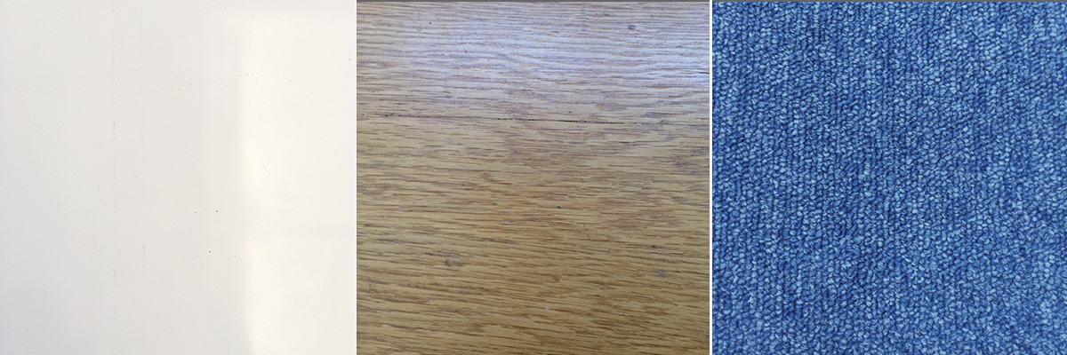
We know that the surface which the robot is placed on affects the control mechanism and therefore three different materials are tested. These are a blank white table, a wooden table and a carpet floor which is shown in the following image.


By inspecting the robots control mechanism we concluded that the best of the three surfaces was the blank white surface and therefore the following tuning and analysis of the PID parameters are performed on this surface.
We have created a standard PID software architecture which makes the replacement of a sensor easy. The architecture is shown in the following image.
...
...
@@ -122,12 +122,23 @@ When the LEGO robot is tilting forward the light sensor will get closer to the s
## Exercise 2, Self-balancing robots with color sensor
### Setup
The robot was assembled according to [3] with some minor modifications. Since the upright motor is not used in the case of a segway
The robot was assembled according to [3] with some minor modifications. Since the upright motor is not used in the case of a segway. An image of the robot is seen in the following image.

| Parameter | Value |
| ------------- |:------:|
| Kp | 7.5 |
| Ki | 10 |
| Kd | 2.5 |
| Offset | 480 |
| Min power | 80 |

## Exercise 3, Self-balancing robots with gyro sensor