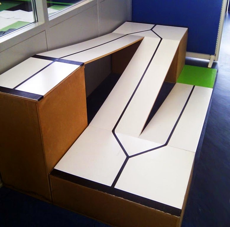
The goal of this lab exercise is to make an autonomous Lego car that drive as fast as possible following the Alishan train track (Figure 1)[1].
Unlike the original Alishan train the car is not supposed to get a “tree”, but is only made to complete the track, getting to the top and getting back down again.
## Plan
Our plan is to make an autonomous robot using two light sensors mounted at the front of the car which will enable us to follow the line as close as possible, in order to reach the top of the track and then reach the bottom as fast as possible.
## Robot
The robot we built uses 2 `light sensors` in order to track the black line (1 sensor on each site of the line). We took the track and split it into different states. The robot should then be able to handle the different states. Figure 2 is a image showing the 7 (including start and end) different states we used in this approach.

At starting up the robot we have to configure black and white for the light sensors as these values are affected by outside light, which means we cannot feed these values beforehand. The first state is the start state. Here we have the robot in the green area awaiting a push on `enter` in order to start the timer, the robot and enter state 0.
State 0. In this state we will handle the first turn. They we we handle this is that we use the left light sensor (seen from the back).
Then each time we start move over we turn a bit to the right. Then we start drifting back towards the black line. So basically we follow the inner side of the line all the way around the corner. Below sees a snippet of the code that makes sure we follow the inner side of the line.
When we have passed the corner we should go to the next state, 1. In order to do so, while we followed the line we used the right light sensor (seen from the back), to count up each time we saw the black line. This we would use to tell us that we have passed the corner and we are ready to do the next turn. Below sees a snippet of code that gives this behavior.
```Java
if(left.readValue() < blackWhiteTreshold) {
times++;
}
if(times > 600) {
times = 0;
command = 1;
}
```
The value 600 is an experimented value. This means that when the right sensor has seen the black line (or what it thinks is a black line) it increment `times`. With this value and the setup of our car it makes sure that we change to state 1, when we need to do the second turn.
In State 1 we will handle the second turn. We come from state 0, where followed the now outer line and we have reach the second turn. Then we change to follow the line with the left light sensor, in order to follow on the inner side of the turn. Below is the code, which looks like the one from state 0, but instead of drifting left and turn right, we now drift right and turn left.
Again we use the same approach as in the previous state to tell when we reach the second state. Here we again use and experimented value that make sure that when we reach the top, we get into state 2. The code is shown below.
```Java
if(right.readValue() < blackTreshold) {
times++;
}
if(times > 400) {
times = 0;
command = 2;
}
```
In state 2 we have reached the top (crossed the line), and we need to make an u-turn. First we tried make this work with sleeps. First making the motor run forward then sleep, then start turn and sleep again and at last drive forward and leave the top floor. After a lot of tries timing the sleeps we gave up. Using sleep was very inconsistent, we couldn't really get it to make a nice u-turn so it could drive back down.
Instead we tried to use the motors`tachoCounter` for a much greater success. So when we entered state 2, we would reset the tacho counter and run forward until the tachocounter said 360 (meaning the wheel had turn one round). Side note, the 360 degrees was just a test at start in order to see how much forward it would go, but it turned to be just fine. After we are done running forward we would reset the tacho counters and set the wheels to run in opposite directions until the tachocounters reach 180 (This would yield a 360 turn). At last we run forward for another 360 on both wheels in order to leave the top and enter the third state. Below is the snippet of code that makes the robot do a u-turn when it reaches the top.
The reason we multiply the `getTachCount` by -1 is that when we want to move our robot forward we use backward, because the motor is set in the opposite direction. So `getTachCount` return it in negative degrees.
State 3 and 4 should work in the same way as 0 and 1, or so we thought. We first tried it like this but when it reached the top, made the u-turn and started moving down it just drove off the edge. So we decided to split the 2 turns on the way down into 2 states. Here we started to run into a lot of trouble. We tried using the same speed we used when we drove up. This did not work well because when it started moving down the speed increased more and more and it drove off the side. We then tried to decrease the speed and make it drift more to the left in order to reach the line so it can follow that and make a inner turn. We did not succeed in doing so. We had a lucky try where it found the line, but did not manage to make proper turn and it drove off the edge again.
The last state is the end state. Here the robot was supposed to stop when it reached the green zone and print out the time it took. Unfortunately we were not able to get this robot to get to the top and then reach the bottom.
We have within the time restraint not been able to solve the robot driving of the edge at the top of the ramp problem. We have tried slowing the robot down further, which had no effect.
The biggest issue seems to be the big change that follows going down instead of up, the robot picks up speed going down (due to gravity) and the light sensors reads slightly different values making our initial calibration a bit off, which might also influence the behaviour of the robot.
It was discussed how to counter this problem but the only reliable solution we could find where to make a new PID controller which should take over after det robot reaches the top and makes the U-turn.
We also discussed using a gyro to change states when going downhill and reaching the platform/turn as we were unable to have enough power on the engines going downhill to actually move the robot when on a flat surface.
The full code for this robot can be found here[2]
Below is a link to a video showing the robot running from the start area and running to the top. Here it make a u-turn and try drives back down but fails to do so.
[Link to video](https://youtu.be/sFsQCRjhr-o)[3]
## Robot 1.1
In an attempt to make the robot climb the ramp more consistently while also completing the task we experimented with some new behavior for the different states. The base idea was that we could spot the turns on the ramp when suddenly reading values equivalent to black with the light sensor. These black readings would always appear a couple of times when turning around along the corner and then stop when we reach a straight section again. To exploit this fact we would then start to measure the time since the last black reading when we got the first one. If 3 seconds passed without getting a new black reading then the robot must have completed the turn and reached second straight part. At this point we would switch from following the right side of the black line to the left side to prepare for the next turn. This means we were now switching from state 0 to state 1 on the middle of the second straight section instead of on the first platform.
Before reaching this solution we experimented with only spotting the sharp 90 degree turn in the middle of the platforms but that proved to be much harder and very inconsistent but the robot could easily miss the turn.
To make the switch to state 1 we simply check if 3 seconds have passed since the last reading of `blackThreshold + 5` or less. This got the robot to the top platform almost every time.
Below you will find a video of the this robot in action. I did a good run this time but it looked like the robot got confused about the light sensor readings at the top and drove off the ramp.
The video can be seen here: http://1drv.ms/1KcTT0p
We had a lot of problems with going downhill since the light sensor readings were very different compared to going uphill. This meant we never actually got the robot to follow the black lines on the straight sections when going downhill. The code for robot 1.1 can be seen here[4].
## Conclusion
At first glance the assignment seemed relatively simple, but as we worked on the project it was clear that this was not a simple line-follower, but instead a complex drive up and down hill, the hills caused many problems that we did not expect making a somewhat trivial assignment much more complex than originally imagined.
Doing our development it became clear that while it might be possible to complete the assignment using a two light sensor build, adding a gyro would make the job easier as we could use this to change our state.
## References
[1], Exercise material lab 8 (http://legolab.cs.au.dk/DigitalControl.dir/NXT/Lesson8.dir/Lesson.html)
