The goal for the day is to make a Lego car follow the Alishan track using a gyroscope and a light sensor.
The goal for the day is to make a LEGO car follow the Alishan track using a gyroscope and a light sensor.
## Plan
## Plan
...
@@ -29,7 +29,7 @@ The flood light is turned on according to results from a previous lesson [2]. A
...
@@ -29,7 +29,7 @@ The flood light is turned on according to results from a previous lesson [2]. A
### Results
### Results
By inspecting the LEGO cars line following behavior we quickly realized that one light sensor is insufficient. The Lego car is only able to follow one edge of the black line. Any deviations from this and the car will perform a 180 degree turn due to the PID implementation. The structure of the track combined with driving up and down requires the LEGO car to be able to approach the black line from both the left and the right side. The solution for this is to implement yet another light sensor.
By inspecting the LEGO cars line following behavior we quickly realized that one light sensor is insufficient. The LEGO car is only able to follow one edge of the black line. Any deviations from this and the car will perform a 180 degree turn due to the PID implementation. The structure of the track combined with driving up and down requires the LEGO car to be able to approach the black line from both the left and the right side. The solution for this is to implement yet another light sensor.
## Implementing two light sensors
## Implementing two light sensors
...
@@ -40,11 +40,13 @@ Two light sensors are placed in the front of the LEGO car pointing downwards. Ag
...
@@ -40,11 +40,13 @@ Two light sensors are placed in the front of the LEGO car pointing downwards. Ag


When the LEGO car is following the black line the two light sensors will be on each side of the line measuring light from the same white surface. Therefore the set point is now changed from 42 to 0 and the error is calculated by subtracting the right sensor value from the left sensor value.
### Results
### Results
The line following capabilities is somewhat improved by adding an extra sensor. The LEGO car now follows the center of the black line instead of an edge. However, the PID regulation is slow. When the LEGO car approaches the black line from an angle the PID regulation is not able to correct for this angle and steer the LEGO car onto the black line. In this case the LEGO car just crosses the line. By inspection the cause of this problem is narrowed down to the motor control which seems relatively slow thereby affecting the PID regulation.
The line following capabilities is somewhat improved by adding an extra sensor. The LEGO car now follows the center of the black line instead of an edge. However, the PID regulation is slow. When the LEGO car approaches the black line from an angle the PID regulation is not able to correct for this angle and steer the LEGO car onto the black line. In this case the LEGO car just crosses the line. By inspection the cause of this problem is narrowed down to the motor control which seems relatively slow thereby affecting the PID regulation.
In the beginning of the lesson it was estimated that the LeJOS `DifferentialPilot` would be the optimal solution for motor control due to its use of the tachometer. Since the turning methods of this class takes a value in degrees and a radius as input it seemed as the obvious choice in order to simply the programming of the turns. When using this class, a speed and an acceleration is defined and in order to steer the `steer()` method is called. This method takes an input from -200 to 200 as input and steers the LEGO car accordingly. The problem is that even at an extreme turn rate (200 or -200) the reaction of the `DifferentialPilot` is too slow to keep the robot on track. Therefore sharp turns are excluded when using the differential pilot.
In the beginning of the lesson it was estimated that the LeJOS `DifferentialPilot` would be the optimal solution for motor control due to its use of the tachometer. Since the turning methods of this class takes a value in degrees and a radius as input, it seemed as the obvious choice in order to simplify the programming of the turns. When using this class, a speed and an acceleration is defined and in order to steer the `steer()` method is called. This method takes an input from -200 to 200 as input and steers the LEGO car accordingly. The problem is that even at an extreme turn rate (200 or -200) the reaction of the `DifferentialPilot` is too slow to keep the robot on track. Therefore sharp turns are excluded when using the differential pilot.
The solution is to change from the `DifferentialPilot` to direct motor control using the leJOS `MotorPort` class. This greatly improves the PID regulation of the LEGO car.
The solution is to change from the `DifferentialPilot` to direct motor control using the leJOS `MotorPort` class. This greatly improves the PID regulation of the LEGO car.
...
@@ -112,7 +114,7 @@ switch (nextAction) {
...
@@ -112,7 +114,7 @@ switch (nextAction) {
break;
break;
}
}
```
```
The FSM is responsible for performing all turns on the track using an instance of the `Car` class provided by the Arbiter. The methods of the `Car` class is described below. By letting the FSM control the stopping mechanism we avoid having a third behavior that uses the light sensor or an additional color sensor to detect when the LEGO car is in the green end zone.
The FSM is responsible for performing all turns on the track using an instance of the `Car` class provided by the Arbiter. By letting the FSM control the stopping mechanism we avoid having a third behavior that uses the light sensor or an additional color sensor to detect when the LEGO car is in the green end zone.
### Results
### Results
...
@@ -121,7 +123,7 @@ With the current setup the car is able to follow the black line on the first inc
...
@@ -121,7 +123,7 @@ With the current setup the car is able to follow the black line on the first inc


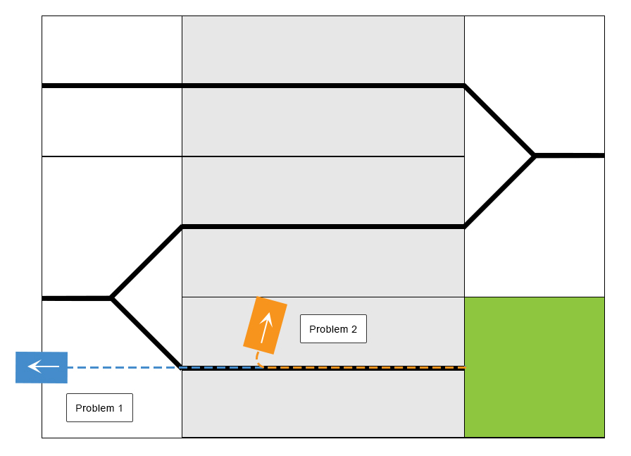
A gyroscope threshold determines whether the PlateauPilot behavior is activated. With the threshold too high the plateau is detected to late (Problem 1) and the LEGO car continues out of the track. With the threshold too low the plateau is detected too early and the LEGO car makes a right turn too soon (Problem 2). It seems to be an impossible task to determine this threshold in the current setting.
A gyroscope threshold determines whether the PlateauPilot behavior is activated. With the threshold too high the plateau is detected to late (Problem 1) and the LEGO car continues out of the track. With the threshold too low the plateau is detected too early and the LEGO car makes a right turn too soon (Problem 2). It seems to be an impossible task to determine this threshold in the current setting.
This indicates that the problem is related to the gyroscope which might not receive enough impact of the incline change when mounted close to the LEGO car in order to determine a sufficient threshold.
This indicates that the problem could be related to the gyroscope which might not receive enough impact of the incline change in order to determine a sufficient threshold.
In this setup the gyroscope is placed relatively low and close to the body of the LEGO car. Due to the gyroscope is measuring angular velocity and not translational velocity it should not make any difference by raising the gyroscope. However, a test is carried out to confirm this.
In this setup the gyroscope is placed relatively low and close to the body of the LEGO car. Due to the gyroscope is measuring angular velocity and not translational velocity it should not make any difference by raising the gyroscope. However, a test is carried out to confirm this.
The `gyroOffset` is set to `600` according to the noise floor of the gyroscope test. The plateau threshold is determined to `40` which seemed sufficient together with a timeout of `2000` milliseconds. The timeout ensures that there must be at least two seconds between each plateau. We thereby avoid having inexpedient state changes caused by two peaks in row.
The `gyroOffset` is set to `600` according to the noise floor of the gyroscope test. The plateau threshold is determined to `40` which seemed sufficient together with a timeout of `2000` milliseconds. The timeout ensures that there must be at least two seconds between each plateau. We thereby avoid having inexpedient state changes caused by two peaks in a row.
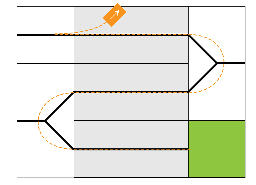
By implementing these modification to the software and tuning the PID parameters and the hard coded turns, the LEGO car is able to drive all the way to the top of the track. On the top plateau the LEGO car performs a 180 degree turn and initiates its way back. Here a new problem arises. Whenever the LEGO car gets off the top plateau it almost immediately makes a left turn as illustrated in the following figure.
By implementing these modifications to the software and tuning the PID parameters and the hard coded turns, the LEGO car is able to drive all the way to the top of the track. On the top plateau the LEGO car performs a 180 degree turn and initiates its way back. Here a new problem arises. Whenever the LEGO car gets off the top plateau it almost immediately makes a left turn as illustrated in the following figure.


...
@@ -174,7 +176,7 @@ The differential pilot seemed to be too high an abstraction level and the direct
...
@@ -174,7 +176,7 @@ The differential pilot seemed to be too high an abstraction level and the direct
## Final setup
## Final setup
It turned out that substituting the direct control of the motors with regulated control had a significantly impact on the performance. After additional tuning of the PID parameters and turn values to the new motor control class the LEGO car was able to travel all the way from the bottom, to the top and back again. This is shown in Video 1 in the references section where the car completes the track in 30.3 seconds. By increasing the default speed we were able to push the completion time down to 27.9 seconds. This is shown in Video 2.
It turned out that substituting the direct control of the motors with regulated control had a significantly impact on the performance. After additional tuning of the PID parameters and turn values to the new motor control class the LEGO car is able to travel all the way from the bottom, to the top and back again. This is shown in Video 1 in the references section where the car completes the track in 30.3 seconds. By increasing the default speed we were able to push the completion time down to 27.9 seconds. This is shown in Video 2.
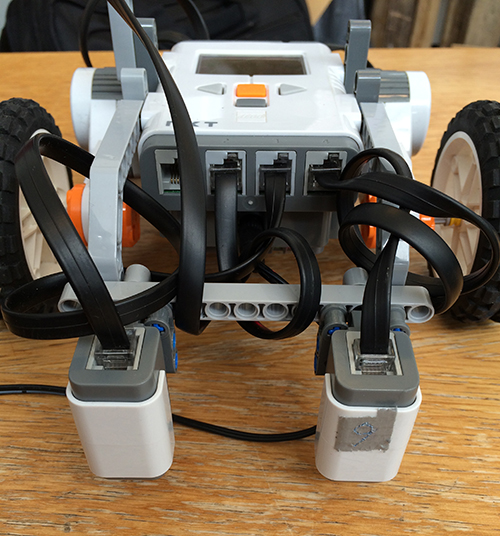
The final construction is shown in the following figure.
The final construction is shown in the following figure.
...
@@ -214,7 +216,7 @@ A link to the final code, [RoboRacerV3], is also found in the references section
...
@@ -214,7 +216,7 @@ A link to the final code, [RoboRacerV3], is also found in the references section
## Conclusion
## Conclusion
An autonomous Lego car application has been implemented which was able to drive up and down the Alishan track in a time of 27,9 seconds, as seen in [Video 2].
An autonomous LEGO car application has been implemented which was able to drive up and down the Alishan track in a time of 27,9 seconds, as seen in [Video 2].
The development process has been characterized by the postulation and verification of various hypotheses during the project.
The development process has been characterized by the postulation and verification of various hypotheses during the project.
At first we attempted a strategy with only a gyro sensor to detect the plateaus, and hard-coding of the turns.
At first we attempted a strategy with only a gyro sensor to detect the plateaus, and hard-coding of the turns.