@@ -21,11 +21,11 @@ The plan for the day is to build upon previous results [1]. It seemed plausible
### Setup
In a previous lesson we used a single light sensor to make the car able to follow the edge of a black line. This is the starting point for this task. The light sensor is mounted in front of the car pointing downwards as seen in the following image.
In a previous lesson we used a single light sensor to make the car be able to follow the edge of a black line. This is the starting point for this task. The light sensor is mounted in front of the car pointing downwards as seen in the following image.

The flood light is turned on according to results from a previous lesson [2]. A test program is made where the steering is controlled by a PID regulator. This program is based on experience gained from exercise 4 [3]. The set point was defined as the middle value between the light sensor reading of white and black respectively. In addition to this we implemented a direct PC connection in order to tune the parameters of the PID regulator.
The flood light is turned on according to results from a previous lesson [2]. A test program is made where the steering is controlled by a PID regulator. This program is based on experience gained from exercise 4 [3]. The set point was defined as the middle value between the light sensor reading of white and black. In addition to this we implemented a direct PC connection in order to tune the parameters of the PID regulator.
### Results
...
...
@@ -36,7 +36,7 @@ By inspecting the LEGO cars line following behavior we quickly realized that one
### Setup
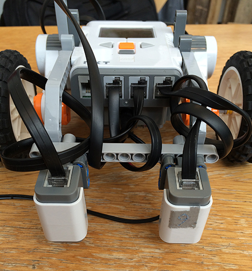
Two light sensors are placed in the front of the LEGO car point downwards. Again the flood light is turned on in both sensors. The setup is shown in the following figure.
Two light sensors are placed in the front of the LEGO car pointing downwards. Again the flood light is turned on in both sensors. The setup is shown in the following figure.

...
...
@@ -44,7 +44,7 @@ Two light sensors are placed in the front of the LEGO car point downwards. Again
The line following capabilities is somewhat improved by adding an extra sensor. The LEGO car now follows the center of the black line instead of an edge. However, the PID regulation is slow. When the LEGO car approaches the black line from an angle the PID regulation is not able to correct for this angle and steer the LEGO car onto the black line. In this case the LEGO car just crosses the line. By inspection the cause of this problem is narrowed down to the motor control which seems relatively slow thereby affecting the PID regulation.
In the beginning of the lesson it was estimated that the LeJOS `DifferentialPilot` would be the optimal solution for motor control due to its use of the tachometer. Since the turning methods of this class takes a value in degrees and a radius as input it seemed as the obvious choice in order to simply the programming of the turns. When using this class, a speed and an acceleration is defined and in order to steer the `steer()` method is called. This method takes an input from -200 to 200 as input and steers the LEGO car accordingly. The problem is that even at an extreme turn rate (200 or -200) the reaction of the 'DifferentialPilot' is too slow, and not extreme enough to keep the robot on track. Therefore sharp turns are excluded when using the differential pilot.
In the beginning of the lesson it was estimated that the LeJOS `DifferentialPilot` would be the optimal solution for motor control due to its use of the tachometer. Since the turning methods of this class takes a value in degrees and a radius as input it seemed as the obvious choice in order to simply the programming of the turns. When using this class, a speed and an acceleration is defined and in order to steer the `steer()` method is called. This method takes an input from -200 to 200 as input and steers the LEGO car accordingly. The problem is that even at an extreme turn rate (200 or -200) the reaction of the `DifferentialPilot` is too slow, and not extreme enough to keep the robot on track. Therefore sharp turns are excluded when using the differential pilot.
The solution is to change from the `DifferentialPilot` to direct motor control using the leJOS `MotorPort` class. This greatly improves the PID regulation of the LEGO car.
...
...
@@ -114,9 +114,7 @@ switch (nextAction) {
```
The FSM is responsible for performing all turns on the track using an instance of the `Car` class provided by the Arbiter. The methods of the `Car` class is described below. By letting the FSM control the stopping mechanism we avoid having a third behavior that uses the light sensor or an additional color sensor to detect when the LEGO car is in the green end zone.
The hardware setup is identical to previously.
The PlateauPilot performs an action every time a plateau is reached. This is sensed using the gyroscope. In the code snippet below the run function of the PlateauPilot is shown. This function sets the boolean ´isPlatueaReached´, which triggers the Arbiter to perform the next action, as described by the state machine above.
The PlateauPilot performs an action every time a plateau is reached. This is sensed using the gyroscope. In the code snippet below the run function of the PlateauPilot is shown. This function sets the boolean `isPlatueaReached`, which triggers the Arbiter to perform the next action, as described by the state machine above.