@@ -14,18 +14,18 @@ The goal for the day is to make a LEGO car follow the Alishan track using a gyro
...
@@ -14,18 +14,18 @@ The goal for the day is to make a LEGO car follow the Alishan track using a gyro
## Plan
## Plan
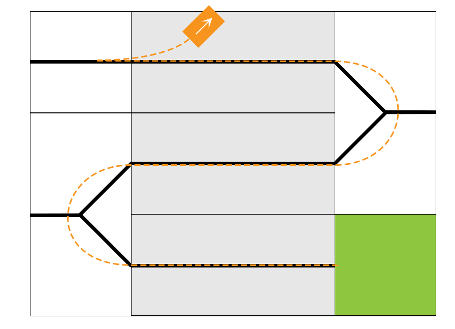
The plan for the day is to build upon previous results [1]. It seemed plausible to use a gyroscope to detect when a plateau is reached however additional sensory needs to be implemented in order for the car to follow the straight inclined paths. The idea is to exploit the black line on these paths and use a light sensor to make the car follow these lines. Behavioral control will be necessary in this setup due to the car having multiple behaviors. It is estimated that hard coding is the optimal solution for the turns do the course of the black line.
The plan for the day is to build upon previous results [1]. It seemed plausible to use a gyroscope to detect when a plateau is reached, however additional sensory needs to be implemented in order for the car to follow the straight inclined paths. The idea is to exploit the black line on these paths and use a light sensor to make the car follow these lines. Behavioral control will be necessary in this setup due to the car having multiple behaviors. It is estimated that hard coding is the optimal solution for the turns do to the course of the black line.
## Implementing a light sensor
## Implementing a light sensor
### Setup
### Setup
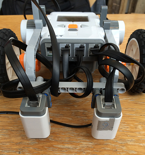
In a previous lesson we used a single light sensor to make the car be able to follow the edge of a black line. This is the starting point for this task. The light sensor is mounted in front of the car pointing downwards as seen in the following image.
In a previous lesson we have used a single light sensor to make the car be able to follow the edge of a black line. This is the starting point for this task. The light sensor is mounted in front of the car pointing downwards as seen in the following image.


The flood light is turned on according to results from a previous lesson [2]. A test program is made where the steering is controlled by a PID regulator. This program is based on experience gained from exercise 4 [3]. The set point was defined as the middle value between the light sensor reading of white and black. In addition to this we implemented a direct PC connection in order to tune the parameters of the PID regulator.
The flood light is turned on according to results from a previous lesson [2]. A test program is made where the steering is controlled by a PID regulator. This program is based on experience gained from exercise 4 [3]. The set point was defined as the middle value between the light sensor reading of a white and a black surface. In addition to this we implemented a direct PC connection in order to tune the parameters of the PID regulator.
### Results
### Results
...
@@ -40,7 +40,7 @@ Two light sensors are placed in the front of the LEGO car pointing downwards. Ag
...
@@ -40,7 +40,7 @@ Two light sensors are placed in the front of the LEGO car pointing downwards. Ag


When the LEGO car is following the black line the two light sensors will be on each side of the line measuring light from the same white surface. Therefore the set point is now changed from 42 to 0 and the error is calculated by subtracting the right sensor value from the left sensor value.
When the LEGO car is following the black line the two light sensors will be on either side of the line measuring light from the same white surface. Therefore the set point is now changed from 42 to 0 and the error is calculated by subtracting the right sensor value from the left sensor value.
### Results
### Results
...
@@ -48,7 +48,7 @@ The line following capabilities is somewhat improved by adding an extra sensor.
...
@@ -48,7 +48,7 @@ The line following capabilities is somewhat improved by adding an extra sensor.
In the beginning of the lesson it was estimated that the LeJOS `DifferentialPilot` would be the optimal solution for motor control due to its use of the tachometer. Since the turning methods of this class takes a value in degrees and a radius as input, it seemed as the obvious choice in order to simplify the programming of the turns. When using this class, a speed and an acceleration is defined and in order to steer the `steer()` method is called. This method takes an input from -200 to 200 as input and steers the LEGO car accordingly. The problem is that even at an extreme turn rate (200 or -200) the reaction of the `DifferentialPilot` is too slow to keep the robot on track. Therefore sharp turns are excluded when using the differential pilot.
In the beginning of the lesson it was estimated that the LeJOS `DifferentialPilot` would be the optimal solution for motor control due to its use of the tachometer. Since the turning methods of this class takes a value in degrees and a radius as input, it seemed as the obvious choice in order to simplify the programming of the turns. When using this class, a speed and an acceleration is defined and in order to steer the `steer()` method is called. This method takes an input from -200 to 200 as input and steers the LEGO car accordingly. The problem is that even at an extreme turn rate (200 or -200) the reaction of the `DifferentialPilot` is too slow to keep the robot on track. Therefore sharp turns are excluded when using the differential pilot.
The solution is to change from the `DifferentialPilot` to direct motor control using the leJOS `MotorPort` class. This greatly improves the PID regulation of the LEGO car.
The solution is to change from the `DifferentialPilot` to direct motor control using the leJOS `MotorPort` class. This greatly improves the responsiveness of the PID regulation.
## Adding behavioral control
## Adding behavioral control
...
@@ -170,9 +170,7 @@ By implementing these modifications to the software and tuning the PID parameter
...
@@ -170,9 +170,7 @@ By implementing these modifications to the software and tuning the PID parameter


It is assumed that the cause of this is found in the direct motor control implementation. Without any motor regulation the LEGO car quickly gains too much speed when driving down the track and the PID regulator cannot cope with this.
It is assumed that the cause of this is found in the direct motor control implementation. Without any speed control of the wheels, the turns quickly get unstable because turning the wheels has a lot less resistance when going downhill. This can be avoided by using a motor driver which keeps track of actual revolutions of the wheels, instead of just the power delivered to each motor. With this in mind, the NXTRegulatedMotor class was chosen to replace the direct motor control.
The differential pilot seemed to be too high an abstraction level and the direct motor control was too low. Therefore a middle ground is chosen for the motor control which is the NXTRegulatedMotor class.
## Final setup
## Final setup
...
@@ -198,7 +196,7 @@ public void Rotate180()
...
@@ -198,7 +196,7 @@ public void Rotate180()
}
}
```
```
When turning on each plateau, the robot must travel along an arc instead of turning around its center. This is not easily implemented using the `rotate()` function, instead each turn is hard coded by imposing a certain speed to each motor in a fixed amount of time. The speed and the time interval is then adjusted according to manual inspection. Turning is different whether the robot is ascending or descending, and left and right turns are not implemented precisely symmetrical, because the left and right motors run slightly different. All turns follow the same pattern and is implemented as follows:
When turning on each plateau, the robot must travel along an arc instead of turning around its center. This is not easily implemented using the `rotate()` function, instead each turn is hard coded by imposing a certain speed to each motor in a fixed amount of time. The speed and the time interval is then adjusted according to manual inspection. Turning is different whether the robot is ascending or descending, and left and right turns are not implemented precisely symmetrical, because the left and right motors run slightly different. All turns follow the same pattern and are implemented as follows: