@@ -121,12 +121,20 @@ When the LEGO robot is tilting forward the light sensor will get closer to the s
...
@@ -121,12 +121,20 @@ When the LEGO robot is tilting forward the light sensor will get closer to the s
## Exercise 3, Self-balancing robots with gyro sensor
## Exercise 3, Self-balancing robots with gyro sensor
### Setup
The code for this exercise is inspired by the code described and linked in [4]. The full implementation can be found at [5], with the corresponding PC program located at [6].
### Results
In order to investigate the properties of the gyro sensor, it was mounted on the shoulder of the robot. The robot was then rotated about 90 degrees in one direction (1. movement), then 180 degrees in the opposite direction (2. movement), then then rotated back 90 degrees to the starting point (3. movement). This procedure was carried out for all three axes, one at a time, as shown in video [Exercise 3.1].
In order to investigate the properties of the gyro sensor, it was mounted on the shoulder of the robot. The robot was then rotated about 90 degrees in one direction (1. movement), then 180 degrees in the opposite direction (2. movement), then then rotated back 90 degrees to the starting point (3. movement). This procedure was carried out for all three axes, one at a time, as shown in video [Exercise 3.1].


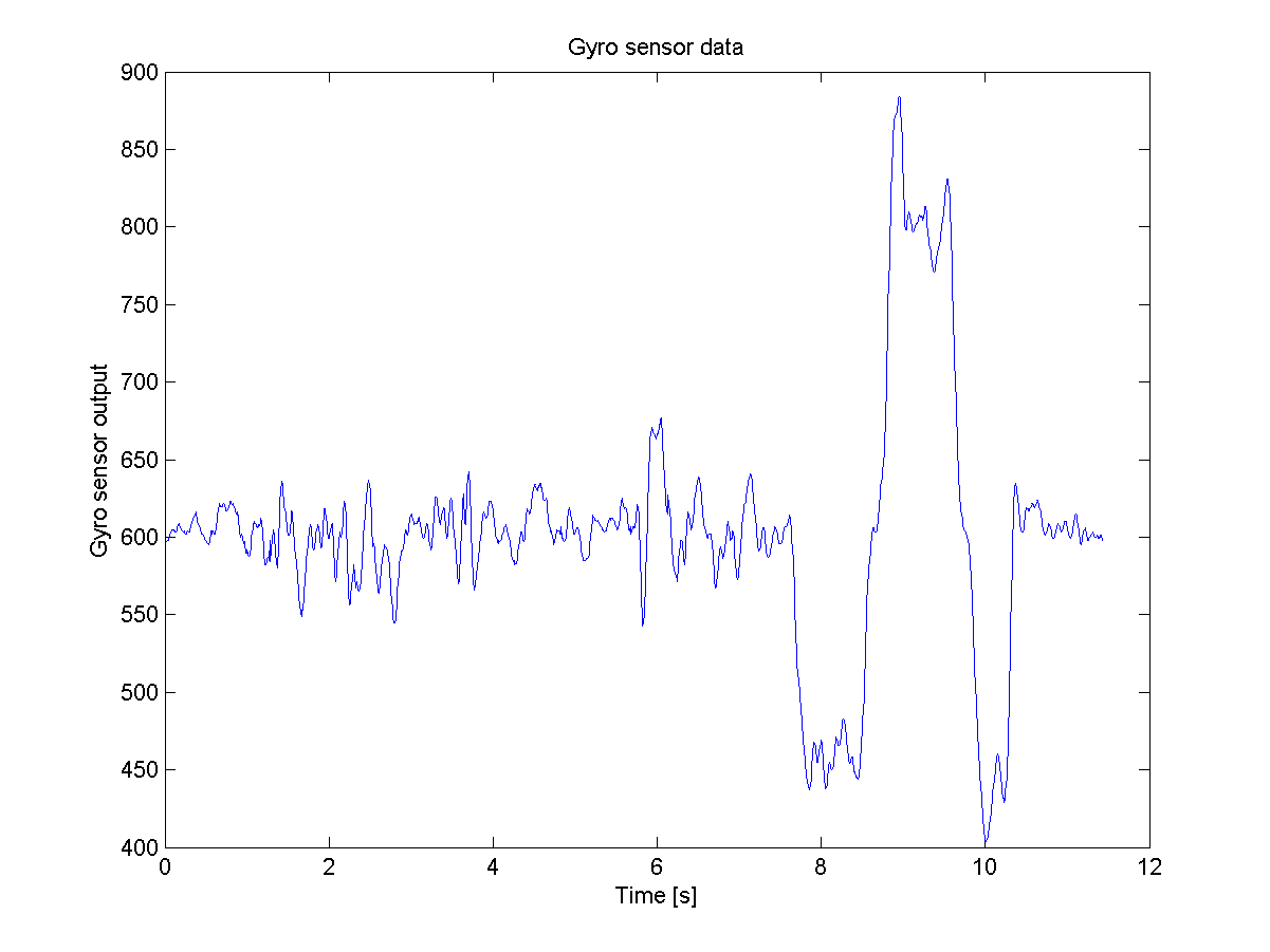
The data shows, that the offset for this sensor is around 600. Furthermore, it can be seen from the data, that the supplied gyro sensor only senses changes to angular velocity in one axis. This can be seen by the three spikes starting just before T = 8. These spikes corresponds the three movements, for a single axis.
The data shows, that the offset for this sensor is around 600. Furthermore, it can be seen from the data, that the supplied gyro sensor only senses changes to angular velocity in one axis. This can be seen by the three spikes starting just before T = 8. These spikes corresponds the three movements, for a single axis.
... drift ..
## Conclusion
## Conclusion
...
@@ -140,6 +148,10 @@ The data shows, that the offset for this sensor is around 600. Furthermore, it c
...
@@ -140,6 +148,10 @@ The data shows, that the offset for this sensor is around 600. Furthermore, it c