@@ -200,7 +200,11 @@ Self-balancing robots with gyro sensor
##### Physical Setup
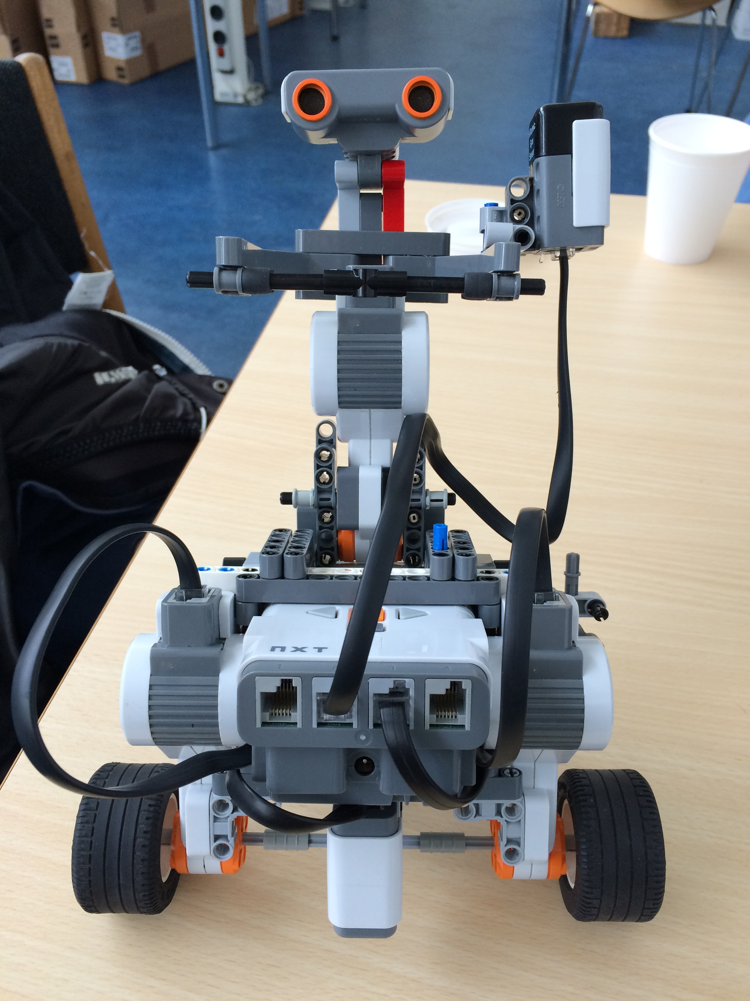
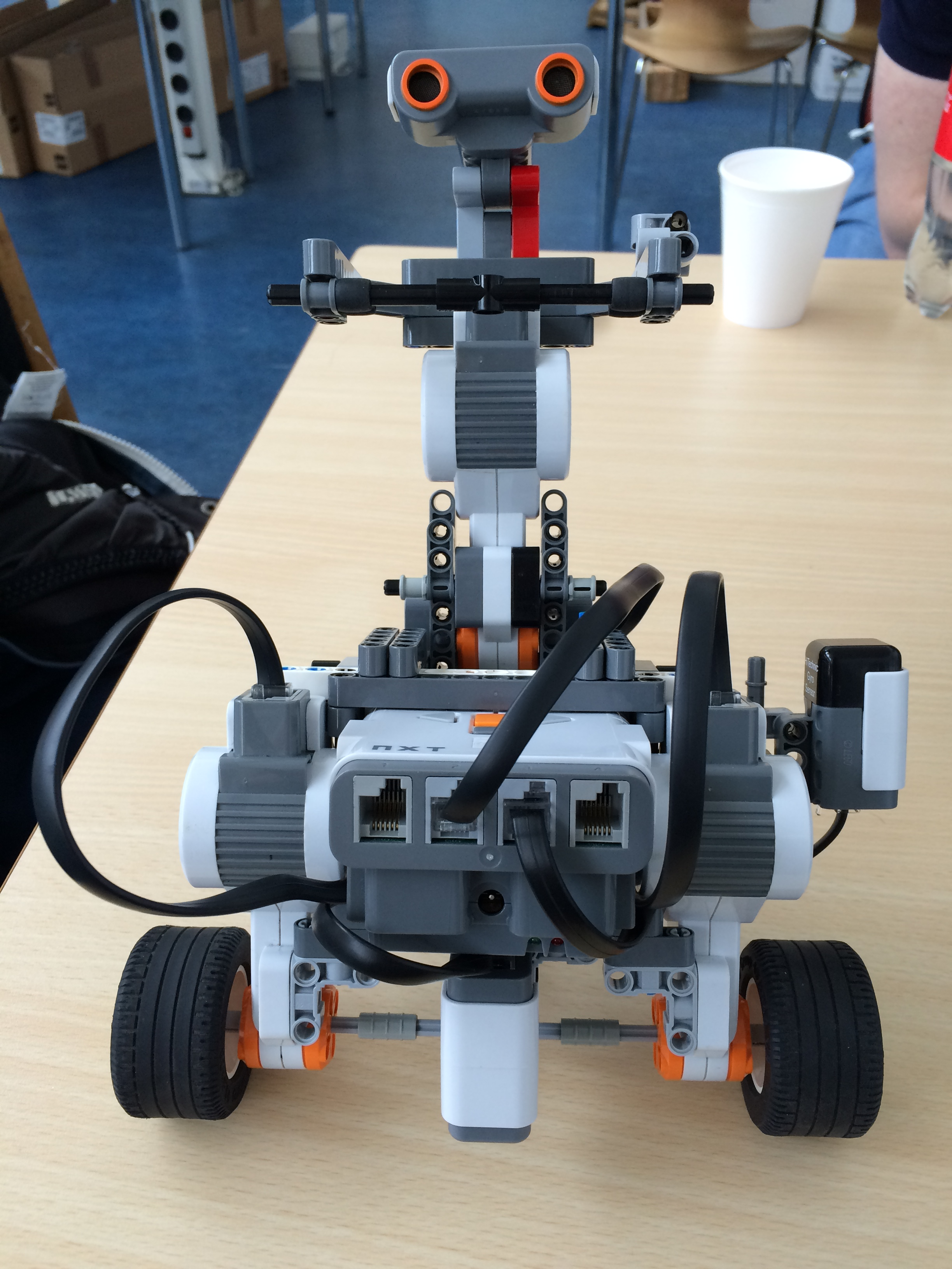
For this exercise, we used the Lego model described in the in "Physical Setup" section for exercise 2 as base. Additionally a gyro sensor was mounted on the robot. During the exercise we tried two different mounting points for the gyro sensor - these are discussed in the "Results" section of this exercise.
##### Software Setup
...
...
@@ -309,14 +313,10 @@ To test the robot and the different gains effect on the robot, as described in t
***KSpeed**: The motor speed gain determines the resistance in the motor. The faster the wheel was spanned, the higher the resistance from the motor.
***KPos**: The motor position gain makes the wheel turn back to its original position. Increasing the gain increases the speed with which the motor turns back to the set-point. If increased to much, the motors starts oscillating.
A possible cause for the erroneous angle could be, that the gyro sensor is more sensitive in the forward direction than backwards, causing a small error on each gyrospeed calculation, which the integration of time then accumulates.
In the first test of the robot, the gyro sensor was placed on the shoulder of the robot(see the pictures below). This gave rise to a lot of fluctuations in the gyro sensor data, due to the fact that robots upper part is very loosely connected to the lower part and therefore shakes a lot.
A possible cause for the erroneous angle could be, that the gyro sensor is more sensitive in the forward direction than backwards, causing a small error on each gyrospeed calculation, which the integration over time then accumulates.
In the first test of the robot, the gyro sensor was placed on the shoulder of the robot(see the pictures in section "physical setup"). This gave rise to a lot of fluctuations in the gyro sensor data, due to the fact that robots upper part is very loosely connected to the lower part and therefore shakes a lot.
In the second part, the gyro sensor was attached to the lower part of the robot. This removed a lot of the high fluctuations due to the tremors.


